Small scale localization using IR
Final Presentation Video
I. Abstract
We explore the possibility of using IR beacons for small-scale relative localization between objects. Each node will have one IR emitter beacon and multiple IR receivers. The beacons will each be equipped with BLE capabilities and an IMU from an Arduino Nano 33 BLE Sense. These beacons will coordinate blinking patterns over BLE such that only one beacon at a time is emitting IR towards the others to be received. Once the receiving beacon measures the IR value it detects, it will pass the measured values through a trained neural network to estimate its distance from the emitter. To generate a symmetric light pattern, we will use a card or irregular lens to scatter the light in a uniform pattern around the beacon. Since each beacon will have an IMU we will further use this to improve localization accuracy, determine directions of motion, and track each object’s heading.
II. Motivation
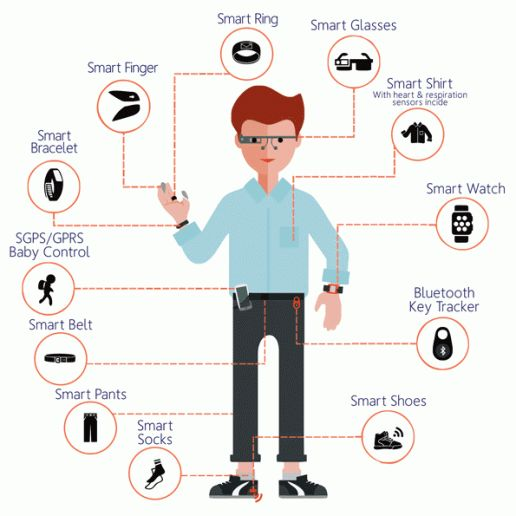
With the increase in IoT devices hitting the market, there is a rising demand for localization between many mobile or wearable devices. For example, Apple is developing many personal, interconnected devices such as the iPhone, iWatch, and Airpods. These devices can benefit from know whether they are currently on the user’s wrist, in their pocket, or far away out of reach. However, traditional localization methods either require stationary beacons or have limited accuracy in a smaller, more personal scale. As a result, these schemes do not work for the growing market of mobile, wearable devices. We aim solve this conflict by designing wireless nodes that can be integrated into devices and enable relative position tracking between similarly networked devices.
III. Prior Work Analysis
There is a large amount of prior work in the realm of indoor localization using IR beacons, but our intended approach of using beacons with changing positions to determine relative positioning seems to be somewhat new.
Indoor IR localization has been used in past work for navigation for robots and UAVs (1, 4, 5). Most of these works use some form of stationary beacons or markers and they range from using a very small number of sophisticated emitters and receiver devices to using a large number of simple markers for navigation. The simplest technique to determine location is to triangulate using distances from known points (2, 3) but there is one source that used servo motors and highly directional receivers to determine angles to a flying object (1). Since our goal is to determine relative location in a 2D plane without adding moving parts to our beacons, we will use a technique similar to the first method with a few added complications due to making the beacons mobile instead of stationary. To use emitter beacons for triangulation, signals from the beacons need to be distinguished from each other. The IR beacons can flash in coded patterns or with different frequencies so they can be separated using signal processing (2, 3). Since our beacons will have BLE, we are planning to coordinate blinking order over BLE to avoid signal processing overhead.
One of the challenges that differentiates our project from other IR localization projects is that we are intending to update relative locations from mobile beacons and each node will both be a beacon and a device that is being tracked. Similar problems to these are addressed in a thesis by Andreas Biri from ETH Zurich using UWB for relative localization (9). This paper describes multidimensional scaling and ways to decrease errors with multiple moving nodes. One of the conclusions from this work is that accuracy will improve significantly when using more than 4 nodes, since this will provide redundancy and correct for errors. Since we are planning to use a smaller number of nodes, we will use the IMU to determine whether a node is moving or stationary and for dead reckoning location tracking to provide redundancy.
In addition to tracking the distance between nodes through IR, we can give each node device an IMU to measure their motion and orientation. Without an accurate heading measurement, we would need 4 or more nodes to track their relative positions. Including an IMU reduces that to 3 nodes with our proposed localization method.
To further utilize the IMU and improve our accuracy, we can use the RoNIN navigation method developed by Sachini Herath to get a second estimation of each node’s positioning (10). The RoNIN method uses a trained neural network to read IMU measurements and track the device’s position over a long period of time. Implemented into our system, we could combine the position data provided by the neural network with our IR data to get a better estimate of each node’s relative position. However, it may be difficult to port the full RoNIN neural network over to our system. Additionally, it will most likely have a high latency on our Arduino platform. Therefore, we plan to use the RoNIN method as an inspiration basis and explore other differential inertial measurement dead reckoning methodologies that use less resources and operate in real time.
Libraries for BLE communication between multiple transmitting and receiving devices exist and are readily usable (6) (updated in strengths and weaknesses section). Additionally, the protocol was designed to minimize energy consumption without introducing significant latency (7). This makes it ideal for our embedded system, which will be powered by batteries and calculating positions in real time. For our system, we will use the ArduinoBLE library to set up our network (8). With this library, each BLE device can simultaneously act as a central or peripheral device, forming a connected network. Any two central devices in the network can transmit and receive to each other by subscribing and posting to a main peripheral’s bulletin boards.
IV. Main Project Components
- Hardware: This project includes a relatively small custom PCB and 3D printed frame.
- Sensor Calibration: IR emitters and receivers are calibrated to gather distance and direction values as soon as the hardware arrives.
- BLE Synchronization: Since we intend to have independent “equal” nodes, we worked out synchronization between beacons without a predefined master node.
- Distance Estimating Neural Network: We implemented a neural network on the Arduinos through Tensorflow Lite to take in our received IR measurements with IMU heading and extrapolate the distance between beacons.
V. Goals and Deliverables
- Each beacon can measure distances from other beacons with accuracy varying by about 5mm without any stationary elements.
- As a beacon moves, its position updates correctly on a relative coordinate system.
- Full transmit and receive between all devices over BLE.
VI. Technical Approach
The beacons will contain identical hardware and be based around the Arduino Nano 33 BLE Sense. These beacons triangulate relative position based on the received IR intensity and the locations of the other beacons. To avoid crosstalk, the beacons will flash in turn in an order coordinated over BLE as shown in Figure 1. Although a standard approach based on distances alone would use 3 stationary beacons and a single moving device, we will attempt to use only 3 devices and handle the additional degrees of freedom using each device’s IMU and/or angle measurements.
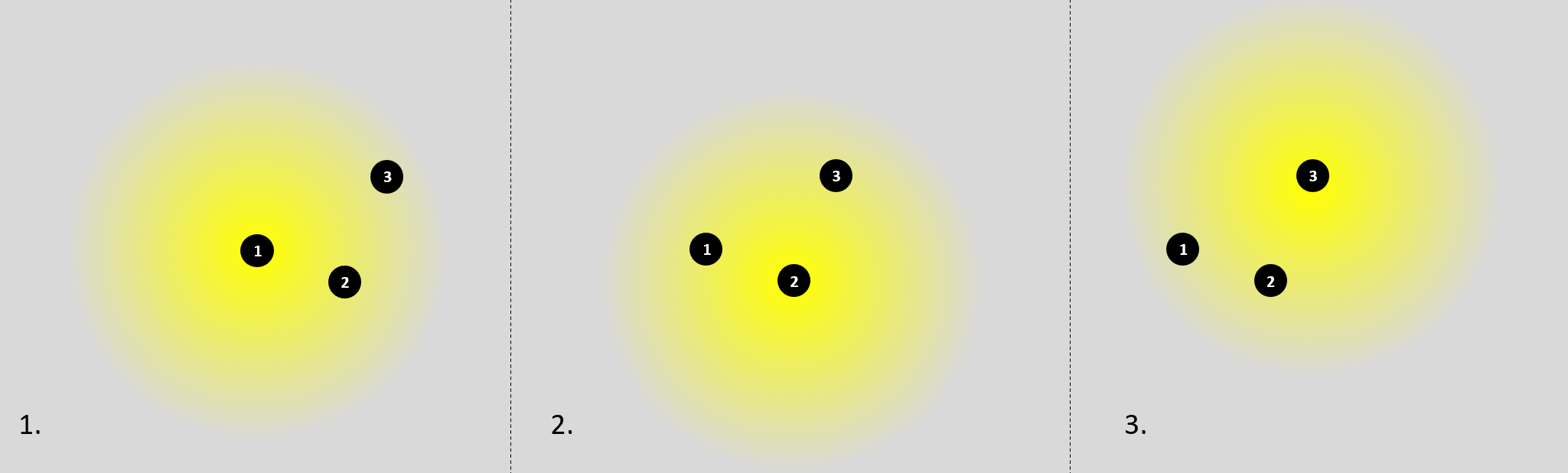 Figure 1: IR Beacons. We will calculate distance based on IR intensity at the receiving beacons.
Our beacon hardware design will include three upward-facing wide-angle IR phototransistors arranged around a single wide-angle IR LED as seen in Figure 2. We chose three phototransistors so that each device can calculate a rough angle measurement as shown in Figure 3. Additionally, each device will have an IMU for orientation tracking. If we are able to determine the angle with a reasonable degree of accuracy, we can leverage the IMU’s magnetometer to calculate a heading and track each device’s angle from one another. Doing so will remove a degree of freedom and reduce the minimum number of nodes from 4 to 3, matching the requirements of the traditional 3 stationary beacon localization.
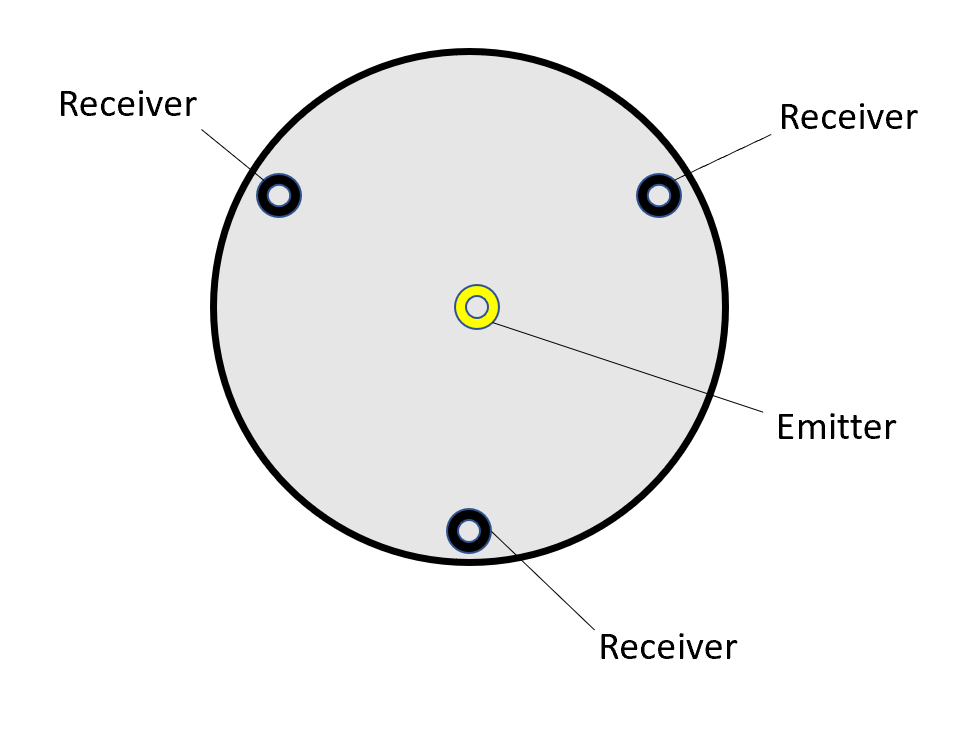 Figure 2: High Level Beacon Design
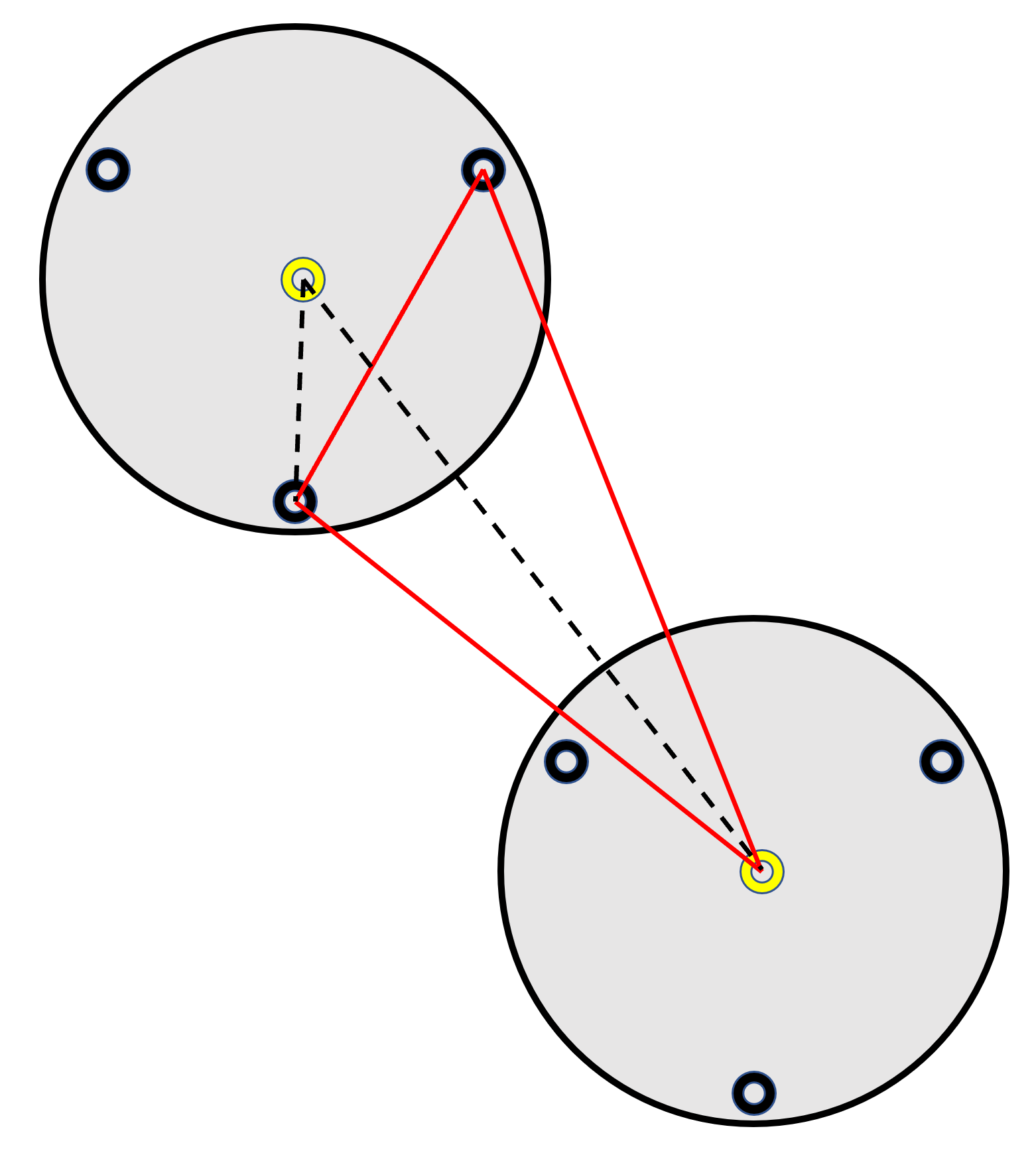 Figure 3: Angle Measurement With Two Receivers on a Single Beacon
To generate a symmetric distribution of light emitted from the beacon, we will use a card of some sort suspended over the emitter to reflect and scatter light as in Figure 4. After assembling the hardware, we will test a couple different ideas to reflect and scatter light. The simplest idea is to simply cut an index card into a circle, but we could also try a cone shape or try attaching aluminum foil to the index card to increase reflection.
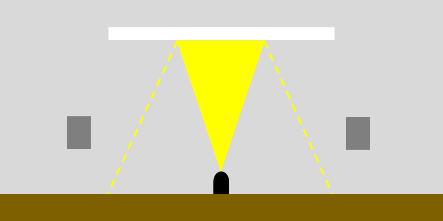 Figure 4: IR Led with Reflector.
Since we are constrained to a small number of beacons due to the cost of additional nanos, we will use the IMU on the Arduino Nano 33 BLE Sense to detect which beacons are moving and will need to update their positions and to implement a dead reckoning system that will provide redundancy and allow us to detect and handle errors in IR distances.
VII. Implementation
Part 1: Hardware and Physical Design
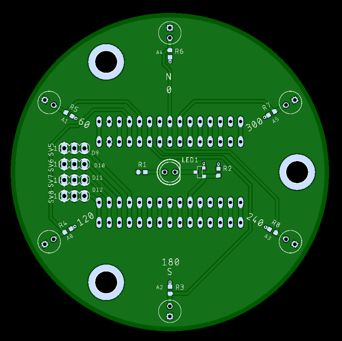
We started by designing the schematic, PCB, and node frames according to our technical approach plan. Each PCB contains the 3 IR receivers and 1 IR emitter mentioned previously with circuits designed to drive them. We chose and ordered our compenents to meet our system’s specs. Once assembled, we validated the performance of the IR emitter and receiver circuits alone without any software control from the microcontrollers.
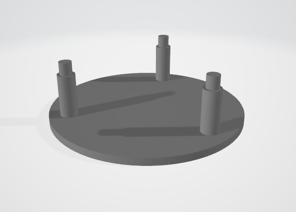
Additionally, we CAD designed a frame to mount our PCB in. The frames keep all of our devices consistent by suspending the electronics and IR reflector at a level height.
Part 2: BLE Communication
Softwarewise, we ran into trouble establishing a connection between more than 2 BLE devices as we originally intended. To work around this issue, we designed our own connectionless BLE network where data is stored and transferred through the broadcasting device’s local name. Figure 4 shows an example of how the network functions. On start up, all the beacons will quickly alternate between broadcasting their unique device ID and scanning for other device IDs. This will allow them to synchronize their communications. Afterwards, the beacons will take turns broadcasting their data. Only one beacon will scan for data each turn, while the others broadcast their measurements. The beacons share a common advertised service UUID that they will use as a key to verify that they are actually IR beacons and not some other random BLE device.
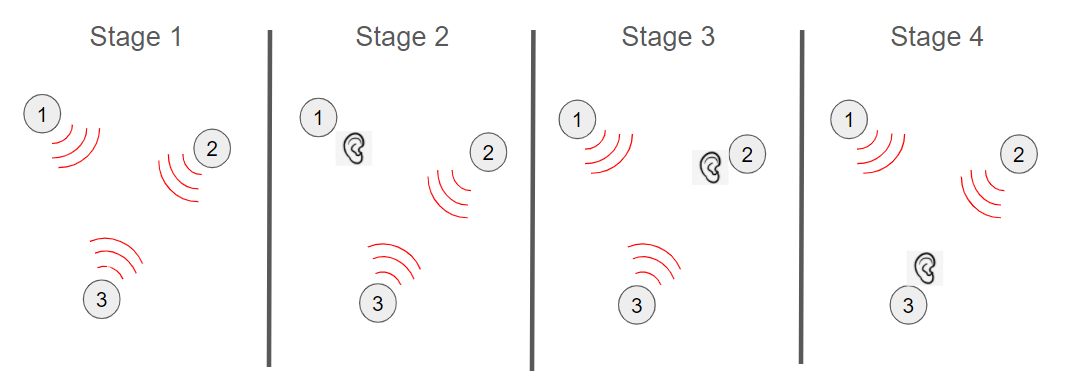 Figure 4: Shows the typical communication flow with 3 nodes. Stage 1 starts the network initialization, then the nodes loop through stage 2-4 with only one beacon scanning at a time.
Part 3: Synchronization
Measuring IR intensity required solving two primary synchronization problems. The first synchronization issue comes from the current limit of the IR led. In order to increase our measurement range, we run more than the rated continuous current though the leds with a 50% duty cycle. This makes a series of bright pulses without burning out the leds. When taking measurements from a remote device this duty cycle means we need to take a series of measurements to ensure at least one measurement is fully located within a high emitter pulse (see Figure 5).
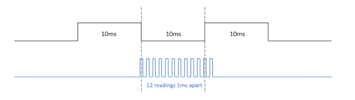 Figure 5: IR Measurement Timing Diagram. This figure shows the timings we used when the testing the beacons without BLE synchronization. Each measurement pulse consists of averaging 40 measurements to decrease noise.
The second synchronization issue is the need to prevent two different IR emitters from being high at the same time. If this happens, IR readings will show misleading information. To solve this, we used the state machine shown in Figure 4. The general idea is that nodes will share their state information and move between the states as they receive confirmation that the other states have completed the desired tasks. After sharing IDs as described in Part 2, each beacon knows the IDs of every other beacon and can sort the IDs in increasing order so all beacons will agree on the order in which they turn on their emitters. The first node selected to emit IR will start in state 0 and all others will start in state 2. From state 0, the node follows these steps. The first node will emit IR until every other beacon confirms having completed a measurement, then it will move to state 1 and listen over BLE until it receives all the measurements taken by the remote nodes. After this, the node relenquishes its position as emitter and moves to state 2 until the next emitter starts emitting. At this point it moves to state 3 where it takes an IR measurement before moving to state 4 where it transmits its reading until the emitter node confirms having received the data. Next, the node moves to state 5 where it will either return to being the emitter node or being a receiver node according to the agreed upon order.
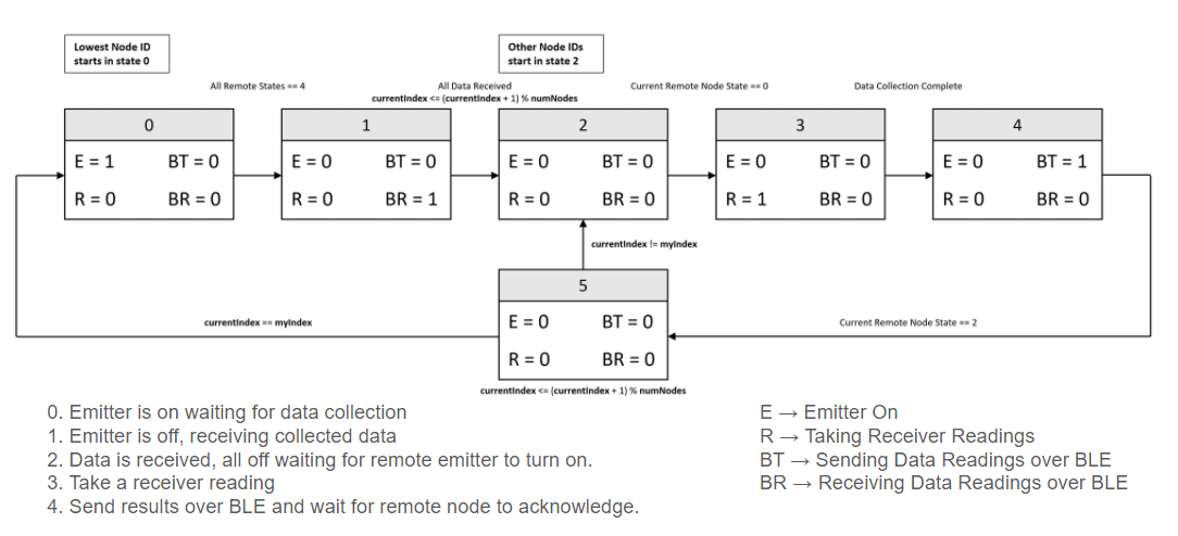 Figure 6: Synchronization State Machine for Broadcaster/Observer Beacon Architecture.
Part 4: Calculating Distance
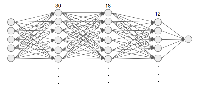
With the BLE network and synchronization established, we collected data between 2 nodes at 3 angles, 3 distances, and 12 remote node orientations to train and validate our distance estimating neural network. We used a fully connected neural network with 3 hidden layers with 30, 18, and 12 neurons respectively to compute distances and angles. The network uses compass and IR readings as inputs from both beacons involved in the measurement. This method showed a great deal of promise accounting for the column interference on our beacons. With the data we collected, distance measurements were good, but angle measurements would benefit from training on a larger data set. We used a 90%-10% training-test split.
Part 5: Visualize and Compare
To easily demonstrate the functionality of our system, we created a script in python to visualize the location of each beacon with respect to a reference. A single beacon is connected through a USB to a computer running the visualizer script. The Arduino will print all of its data to the computer’s COM port, where the script with parse the data and animate the beacons on a 2D coordinate system. Figure 7 shows two screenshots from the script along with an example of what the physical layout of beacons should look like.
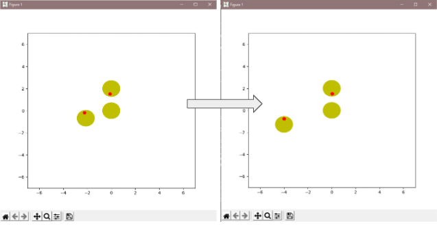
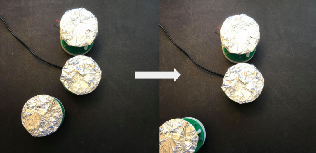 Figure 7: Two screenshots of the visualizer script that were set up to show what the movement of a beacon should look like physically and graphically. We were not able to test test distance measurement in an actual experient due to the BLE and power issues.
VIII. Results
Part 1: Hardware and Physical Design Validation
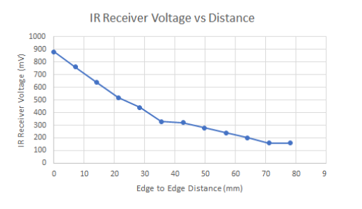
We measured the voltage output of our IR receiver circuits against one IR emitter to verify whether the circuits met out specifications. We used a hand mirror as an ideal reflector and took measurements in a dark room to eliminate any interferance from other sources. The results for the circuit consistency, receiver variance, and emitter symmetry are summarized below. We were also able to verify an approximately exponential relation between the measured voltage and the distance between beacons. These results indicate that our hardware and physical design meets our expectations.
| Metric | Max Percent Error |
|---|---|
| Consistency | 4.7% |
| Receiver Variance | 5.8% |
| Emitter Symmetry | 10.5% |
Part 2: BLE Network
Our unconventional BLE network accomplishes the original goals. It can support multiple nodes in one network and fully transfer and receive data between every node. However, the additional latency severely hinders the rest of the system, where it can take an average of 8 seconds to make one full round of transferring data between every node.
Part 3: Distance Estimation
We were able to validate our fully trained neural network for distance and heading estimations against collected measurements and received pretty good accuracy. Figure 8 shows how our network’s distance estimation loss converges towards 0 after it was trained with our base measurements. Figure 9 shows how our network’s heading estimation loss reaches less than 0.25 after training. Although we weren’t able to test the neural network’s in a real experiment setting due to the BLE and power issues, these loss charts provide a proof of concept for our system could accurately measure distances and headings to meet our original goals.
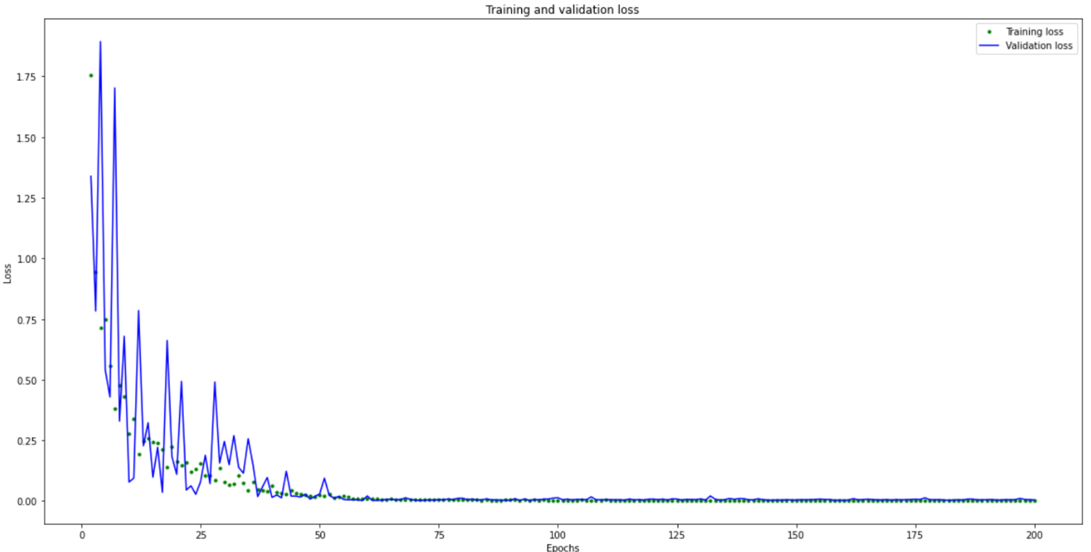 Figure 8: Loss chart for distance estimation when testing the neural network with our validation data at various stages of training.
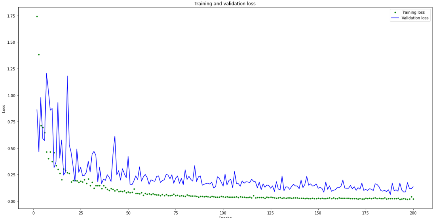 Figure 9: Loss chart for heading estimation when testing the neural network with our validation data at various stages of training.
IX. Strengths and weakness, and future directions
Previously, we assumed that the Arduino BLE library would be able to support multiple devices on one network. However, the latest version of the Arduino BLE library is not capable of this and the developers are actively working on adding these features in later versions. In the future, instead of using our connectionless BLE network, we could use a different wireless communication protocol, such as WiFi.
The Arduino’s 5V-3.3V regulator module can not source enough current to meet our design’s goal. We realized that the Arduinos would crash while collecting data, especially when driven through a USB splitter adaptor that would further limit our current. To account for this, we adjusted our software to spread out our high current operations to reduce our average power. In terms of design, we could completely resolve this by using LiPo batteries as our voltage source and using a separate 5V-3.3V regulator that can support higher output current.
The 3D printed frame could be redesigned to avoid pillars that reflect and block IR emissions. Instead of using the typical off-the-self PLA that we used for the current design, we could use a different material that is transparent to IR, such as the plastic used on IR-based TV remotes.
X. Teammate Contributions
Alex: Neural Network, PCB design, IR control code.
Kenny: 3D printing, BLE code, project website, visualizer script.
XI. Maintaining Safe Social Distancing
Since the IR beacons were relatively inexpensive, we designed and ordered enough for the both of us to use without having to meet in person. We designed and order the boards and parts early with the intent for each of us to have components totaling 5 beacons. In addition to the 2 Arduino Nano 33 BLE Sense modules we own, we borrowed 3 and purchased 1 more. This gave each of us access to 3 BLE/IMU modules to go with 5 IR beacon nodes. We shareed code and hardware designs on github and used Zoom for brainstorming and troubleshooting meetings.
XII. Other Links
Midterm Presentation
Final Presentation
XIII. Sources
(1) Kirchner, Nathan. Infrared Localisation for Indoor UAVs. Research Gate, 2005, researchgate.net/publication/252825877_Infrared_Localisation_for_Indoor_UAVs.
(2) Eric Brassart GRACSY. Groupe de Recherche sur l’Analyse et la Commande des SYstèmes, et al. “Localization Using Infrared Beacons.” Robotica, 1 Mar. 2000, dl.acm.org/doi/10.1017/S0263574799001927.
(3) Raharijaona, Thibaut, et al. “Local Positioning System Using Flickering Infrared LEDs.” MDPI, Multidisciplinary Digital Publishing Institute, 3 Nov. 2017, www.mdpi.com/1424-8220/17/11/2518/htm.
(4) K R Shankar, et al. A Review on IR Beacon Based Mobile Robot Localization - IEEE Conference Publication, IEEE, 2017, ieeexplore.ieee.org/document/7931898.
(5) Lee, Jae-Y, et al. A Real-Time Localization System Based on IR Landmark for Mobile Robot in Indoor Environment. Journal of Institute of Control, 2006, www.researchgate.net/publication/315692392_A_Real-time_Localization_System_Based_on_IR_Landmark_for_Mobile_Robot_in_Indoor_Environment.
(6) Guo, Zonglin, et al. An on-Demand Scatternet Formation and Multi-Hop Routing Protocol for BLE-Based Wireless Sensor Networks. IEEE, 2015, ieeexplore.ieee.org/abstract/document/7127705.
(7) Treurniet, Jan Jaap, et al. Energy Consumption and Latency in BLE Devices under Mutual Interference: An Experimental Study. IEEE, 2015, ieeexplore.ieee.org/abstract/document/7300836.
(8) “ArduinoBLE.” Arduino, www.arduino.cc/en/Reference/ArduinoBLE.
(9) Andreas, Biri. Localizing Mobile Nodes in a Relative Coordinate System. Institute of Information Security, 2017, n.ethz.ch/~abiri/download/Theses/abiri_semester_thesis_1.pdf.
(10) Herath, Sachini, et al. RoNIN: Robust Neural Inertial Navigation in the Wild: Benchmark, Evaluations, & New Methods. IEEE, 2020, ieeexplore.ieee.org/abstract/document/9196860?casa_token=4WmmRORA2QQAAAAA:iOOFTQS93sPSI0iWvwYh9oqWRfsBjfUxqikYEWXALpCwhNK25Lx-uWKcr2RJIAN2YCjV8mT0pwvp.
(11) Mishra, Manasi. “Rise of Wearables and Future of Wearable Technology.” Medium, Medium, 22 Aug. 2018, medium.com/@manasim.letsnurture/rise-of-wearables-and-future-of-wearable-technology-1a4e38a2fbb6.
(12) Tensorflow Lite Example https://github.com/tensorflow/tensorflow/tree/master/tensorflow/lite/micro/examples/magic_wand